

(vii) Shapes of molecules and polyatomic ions
(viii) Transition Metal Configuration and Oxidation States
In 1916 Gilbert Newton Lewis recognised that in simple molecules there had to be an alternative to ionic bonding and suggested that electrons could be shared in pairs to allow atoms to attain the full octet / noble gas structure.
Lewis electron dot diagrams are used to represent electron pairs in molecules and in polyatomic ions.
For normal use this is drawn Cl-Cl, with a single line to show the single bond present.

Covalent bonding usually involves elements close together in the periodic table resulting in little or no electronegativity difference. Ionic bonding generally involves metals from the left hand side and non-metals from the right hand side of the table resulting in a large difference of electronegativity.
This difference in electronegativity puts covalent and ionic bonding at two ends of a spectrum with polar covalent being found somewhere in between.

Polar Covalent Bonds
In a polar covalent bond, the electrons are not shared equally between the atoms.
Identical atoms share the electrons in a covalent bond equally. However, if the two atoms are not identical the bonding electrons are not equally shared and are pulled closer to one of the atoms. When this occurs the bonding is said to be polar covalent.

The atom with the higher electronegativity (chlorine) will have a slight negative charge compared to hydrogen (see data booklet page 10).
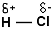
δ - is the greek letter delta meaning 'slightly'.
In some symmetrical molecules the polar nature of the bonds tends to cancel out.
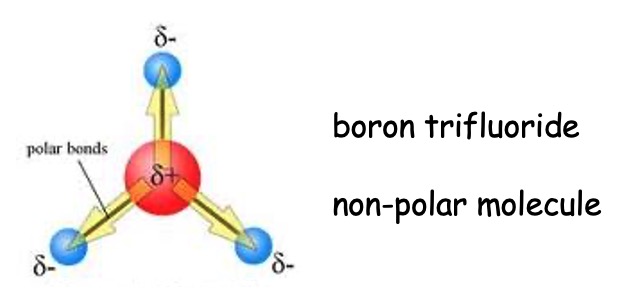
The shapes of molecules or polyatomic ions can be predicted from the number of electron pairs involved in bonding in the valence (outer) shell and the number of lone pairs it has.
When drawing molecules we need to know that non-bonding pairs of electrons (lone pairs) take up more space. This is because the repulsive effect of a lone pair is greater than that of a bonding pair and so the shape of the molecule becomes one in which the lone pairs are as far away as possible.
Bonded:bonded pair < bonded:lone pair < lone pair:lone pair
This is called the valence-shell electron-pair repulsion theory (VSEPR) which is a lot easier than the name suggests.
Molecules take the shape of one of the following structures. Complete the table with the structure of each shape. The first one is completed for you.
| Number of filled orbitals | Diagram | Shape |
|---|---|---|
| 2, AX2 | X - A - X | Linear |
| 3, AX3 | Trigonal Planer | |
| 4, AX4 | Tetrahedral | |
| 5, AX5 | Trigonal Bipyramidal | |
| 6, AX6 | Octahedral |
REMEMBER
1. Draw the structures of the following molecules:
(i)BF2-
(ii) H2O
2. Compare the two structures that you have drawn.
3. Similarly compare CH4 and NH3.
The following table shows the angles found in each structure, complete the name of each structure.
| Number of electron pairs | Arrangement | Angle in degrees | Example |
|---|---|---|---|
| 2 | Linear | 180 | Cl2 |
| 3 | 120 | BF3 | |
| 4 | 109.5 | CH4 | |
| 5 | 90, 120, 180 | PCl5 | |
| 6 | 90 | SF6 |
What effect do bonding and non-bonding pairs of electrons have on the shape of covalent molecules and polyatomic ions?
In molecules with non bonding pairs this angle between molecules decreases slightly due to the greater repulsion from the lone pairs compared to bonding electron pairs.
e.g. the angle between the hydrogens in ammonia is only 107o instead of 109.5o.
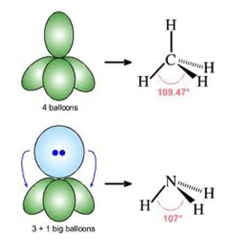
If we think of the lobe of a lone pair as an extra big balloon in comparison to the skinny lobes of a bonding pair. We can see that the big balloon pushes (due to lone pairs having greater repulsion) which decreases the angle in the bonding pairs.
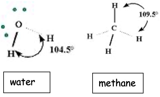 We can see the effect of repulsion from the lone pairs in water also compared with the basic tetrahedral shape of methane from which it comes.
1. What geometry would you expect of tellurium tetrachloride, TeCl4?
2. Xenon tetrafluoride, XeF4 exists.
(a) What sort of bonding might be found in xenon tetrafluoride?
(b) What geometry would you expect of xenon tetrafluoride?
Covalent bonding occurs when the positive nuclei of two atoms are held together by their common attraction for a shared pair of electrons.
A covalent bond is formed when atomic orbitals overlap to form a molecular orbital.

The potential energy change that this produces is shown in the graph below.
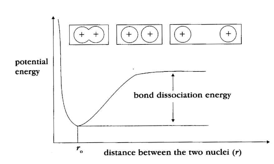
ΔH - Bond enthalpy or bond dissociation energy is the energy required to break one mole of the bonds formed.
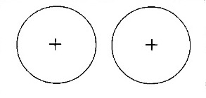
As the atoms approach each other the potential energy gets lower and lower (going along the potential energy the curve from right to left). This decrease continues until the atoms reach their optimum distance apart, where the potential energy is lowest.
The distance between the nuclei at this minimum energy is the bond length ro. This is the normal distance between the nuclei in this molecule.
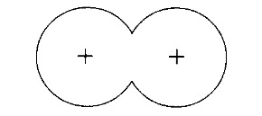
This bond length is due to the common attraction of the nuclei for the shared region of electron density.
If the atoms were to get too close the repulsion of the positive charges in the nuclei becomes important and the potential energy increases again (as seen on the graph, to the left of ro).
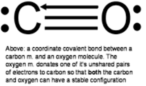
Dative covalent bonds are formed when both electrons making up a covalent bond come from the same atom.
Both oxygen and nitrogen have lone pairs (non bonding pairs of electrons) which have a powerful influence on their chemistry. In some cases a lone pair from one atom contributes both electrons to make the covalent bond.
This is co-ordinative or dative covalent bonding.
e.g. BCl3.NH3 is a stable complex
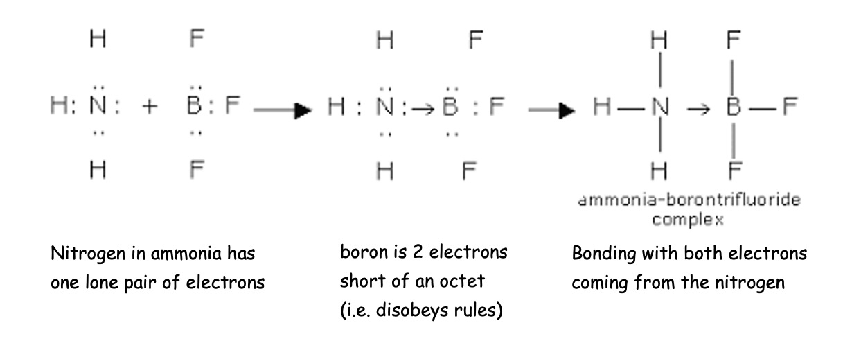
The dative bond can be drawn as an arrow from the donor to the acceptor or with a negative sign on the acceptor and a positive sign the donor.
Another example is carbon monoxide in which oxygen is a donor.
A d-block transition metal have an incomplete d-subshell in at least one of their ions.
The filling of the d-orbitals follows the Aufbau principle - filling orbitals of lowest energy first. (4s before 3d)
Why do chromium [Ar] 3d5 4s1 and copper [Ar] 3d10 4s1 appear not to follow this rule?
The oxidation state tells us the actual charge on an atom if it existed as a monatomic ion. The following rules are used to determine the oxidation state.
Many stable compounds exist with transition metals in different oxidation states. Compounds of the same transition metal in different oxidation states may have different colours.
The stability of transition metal oxidation states is determined by:
Oxidation can be defined as an increase in oxidation number. Reduction can be considered as a decrease in oxidation number.
The table below shows some common oxidation numbers of transition metals with 3d electrons:
| Oxidation State | Metal Symbol | |||||||||
|---|---|---|---|---|---|---|---|---|---|---|
| Sc | Ti | V | Cr | Mn | Fe | Co | Ni | Cu | Zn | |
| +1 | x | |||||||||
| +2 | x | x | x | x | x | x | x | x | x | |
| +3 | x | x | x | x | x | x | x | x | ||
| +4 | x | x | x | |||||||
| +5 | x | |||||||||
| +6 | x | x | x | |||||||
| +7 | x | |||||||||
A complex consists of a central metal ion surrounded by ligands.
Ligands are electron donors and may be negatively charged ions or neutral atoms but must contain an atom with lone pair (non-bonding pair) of electrons which can form a dative (co-ordinative) bond with a metal ion. (Remember in dative bonds, both electron making up the covalent bond come from the same atom.)
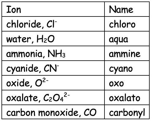
If the ligand can only form one dative (co-ordinative) bond then it is classified as monodentate ('one toothed'). Common ones include the following;
Complete the table drawing the structure of each ligand showing the lone pair and charge where appropriate.
| Ion | Name | Structure |
|---|---|---|
| chloride, Cl- | chloro | |
| water, H2O | aqua | |
| ammonia, NH3 | ammine | |
| cyanide, CN- | cyano |
If the ligand can simultaneously form more than one dative bond it is called a polydentate ligand. Some important bidentate ('two toothed') ligands include,
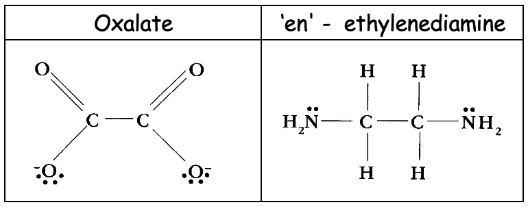
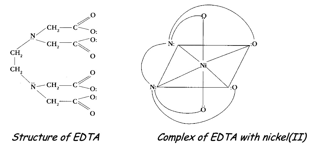
Chelating ligands (chain-like) are polydentate ligands which are able to form more than one bond simultaneously with the same metal ion.
EDTA4- - the ethylenediaminetetraacetate ion is a hexadentate ligand which forms very stable complexes with metals.
The number of bonds the central metal ion can form with ligands is known as the coordination number. For example, in [Cu(H2O)6]2+ the copper(II) is surrounded by six water molecules so will have a coordination number of 6. In [CuCl4]2- there are four chloride ions acting as ligands around the copper (II) ion and so the copper(II) ion in this complex has a co-ordination number of 4.
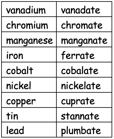
Complexes are written and named according to IUPAC rules.
Most transition metals form coloured complexes. The compounds are coloured because they absorb radiation from the visible part of the spectrum.
Complexes of transition metals can absorb light because the d-orbitals of the transition metal split and are no longer degenerate (of the same energy). When the metal is surrounded by ligands an electrostatic repulsion will raise the energy of any electron in orbitals pointing along these axes. Electrons in any orbitals pointing between axes will be less affected. Resulting in the previously degenerate orbitals (of the same energy) being split as shown.
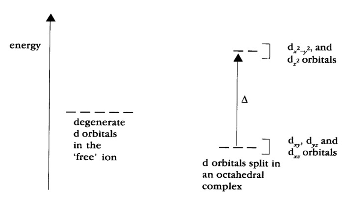
The difference in energy between the two sets of orbitals (d-d transition) is called the crystal field strength (Δ).
Transition metal complexes are therefore coloured because they are able to absorb light when an electron is excited from the d-orbitals of the lower energy (ground state) to d orbitals of higher energy (excited state).
The energy difference between the sets of d orbitals depends on the position of the ligand in the spectrochemical series.

A 'stronger' ligand will displace a 'weaker' one from a metal ion.
Ligands that cause a large difference in energy between subsets of d orbitals are strong field ligands. Weak field ligands cause a small energy difference.
Colours of many transition metal complexes can be explained in terms of d-d transitions. Light is absorbed when electrons in a lower energy d orbital are promoted to a d orbital of higher energy.
The effects of d-d transitions can be studied using ultra-violet and visible absorption spectroscopy. The wavelength for ultra-violet light is approximately 200-400 nm and 400-700 nm for visible.
Absorption of energy in the ultraviolet and visible regions of the spectrum causes transitions between electronic energy levels in atoms, molecules and ions. This energy difference corresponds to region of the electromagnetic spectrum involved and is greatest when ultraviolet is absorbed because ultra violet radiation has a lower wavelength (200 - 400 nm) and therefore higher energy than visible radiation.
Transition metal complexes are coloured because they absorb in the visible spectrum. If a compound absorbs solely in the ultraviolet it will appear colourless as our eyes are unable to detect that ultra violet radiation has been absorbed.
Ultra-violet/visible spectroscopy is a useful analytical tool. The sample used in solution is placed in a 'cell' cuvette. This is compared to an identical cell containing pure solvent. Radiation is scanned continuously through both samples and the spectrometer compares the two beams.
The absorption band for the cyan (blue-green) [Cu (H2O)6]2+ ion, found in aqueous solutions of copper(II) sulphate and copper(II) chloride is shown below.
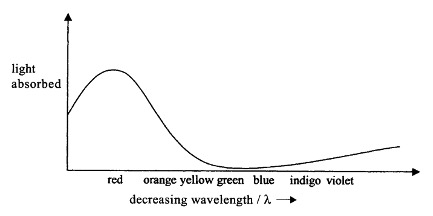
The [Cu(H2O)6]2+ ion has an absorption band in the red part of the visible spectrum. Since red light is absorbed, blue and green light are transmitted which is why the aqueous copper(II) salts appear blue - green (cyan) to our eyes.
Transition metals or their compounds act as catalysts in many important biological and industrial chemical reactions.
| Process | Catalyst Used |
|---|---|
| Haber Process | iron |
| Contact (to make sulphuric acid) | vanadium(V) oxide |
| Ostwald (to make nitric acid) | Platinum |
| Catalytic converter in car exhaust | platinum, palladium and rhodium |
| Preparation of methanol | copper |
| Manufacture of margerine | nickel |
| Polymerisation of alkene | titanium compounds |
Many transition metals act as catalysts because of their ability to exist in a variety of different oxidation states.
The transition metal then reverts back (unchanged) to its original oxidation state once the reaction is complete.
Heterogeneous catalysts are in a different physical state to the reactants being catalysed. Heterogeneous catalysis can be explained in terms of the formation of activated complexes and the adsorption of reactive molecules onto active sites. The presence of unpaired d electrons or unfilled d orbitals is thought to allow activated complexes to form. This can provide reaction pathways with lower activation energies compared to the uncatalysed reaction.
Homogeneous catalysts are in the same physical state to the reactants being catalysed. Homogeneous catalysis can be explained in terms of changing oxidation states with the formation of intermediate complexes.